
BELAN Automation: Rotary, Die and Multi‑Axis Servo — How to Choose the Right Bending Method for Your Copper‑Aluminum Busbar Bending Machine
Industry Background
In new‑energy vehicles, energy‑storage systems, electrical control cabinets and high‑voltage power distribution systems, copper‑aluminum busbars are developing toward multi‑angle, three‑dimensional and complex structures with small‑batch and multi‑specification production features. When selecting a copper aluminum busbar bending machine, manufacturers should not only focus on the maximum processing size or bending angle, but also evaluate how different bending solutions affect machining precision, surface protection, product change‑over efficiency and complex 3D forming capacity. At present, four mainstream bending solutions are widely applied in the market: rotary bending, die bending, servo‑driven rotary bending and multi‑axis linkage bending. Each mechanism fits distinct workpiece types and delivers greatly different actual processing performance.
Four Common Bending Methods for Copper‑Aluminum Busbars
1. Rotary Bending: Flexible Structure for Continuous Forming
Rotary bending shapes copper or aluminum busbars to preset angles through the rotation of bending actuators. This method enables relatively continuous forming without frequent die replacement for each bending angle, delivering outstanding flexibility for multi‑angle workpieces. Nevertheless, the forming capability of standard rotary structures is restricted by actuator quantity and motion logic. When workpieces require a quick switch between flat bending and vertical bending or two bends are spaced at an extremely short distance, auxiliary stations become a decisive factor for stable production.
2. Die Bending: Mature Process With Die‑Dependent Changeover
Die bending applies pressure via customized molds to bend busbars to target angles. Its biggest merit lies in proven technology and stable forming quality for large‑batch production of standardized parts. However, die bending has obvious drawbacks: - Separate molds are required for different workpieces - Extra costs are generated from mold procurement and maintenance - Mold swapping is mandatory for frequent product changeovers - Limited flexibility for continuous forming of complex 3D profiles - Long changeover downtime for small‑batch multi‑variant orders Die bending works well for manufacturers producing highly standardized busbars with fixed geometries. For frequently‑updated new‑energy applications, you need to carefully evaluate the overall die‑swap costs before making your decision.
Servo‑Driven Rotary Bending: Higher Precision & Automation
Servo‑rotary bending upgrades traditional rotary structures by adopting servo motors for closed‑loop motion control. Compared with conventional mechanical bending, servo systems precisely regulate: - Bending angle - Bending speed - Position coordinates - Acceleration & deceleration curve - Synchronization of multi‑step motions Copper‑aluminum busbars demand both reliable electrical conductivity and consistent dimensional tolerance. Servo control eliminates deviations caused by manual parameter tuning. Once a machining program is saved, operators can directly recall the parameters, greatly improving dimensional consistency across production batches.
Multi‑Axis Linkage Bending: Core Solution for Complex 3D Busbars
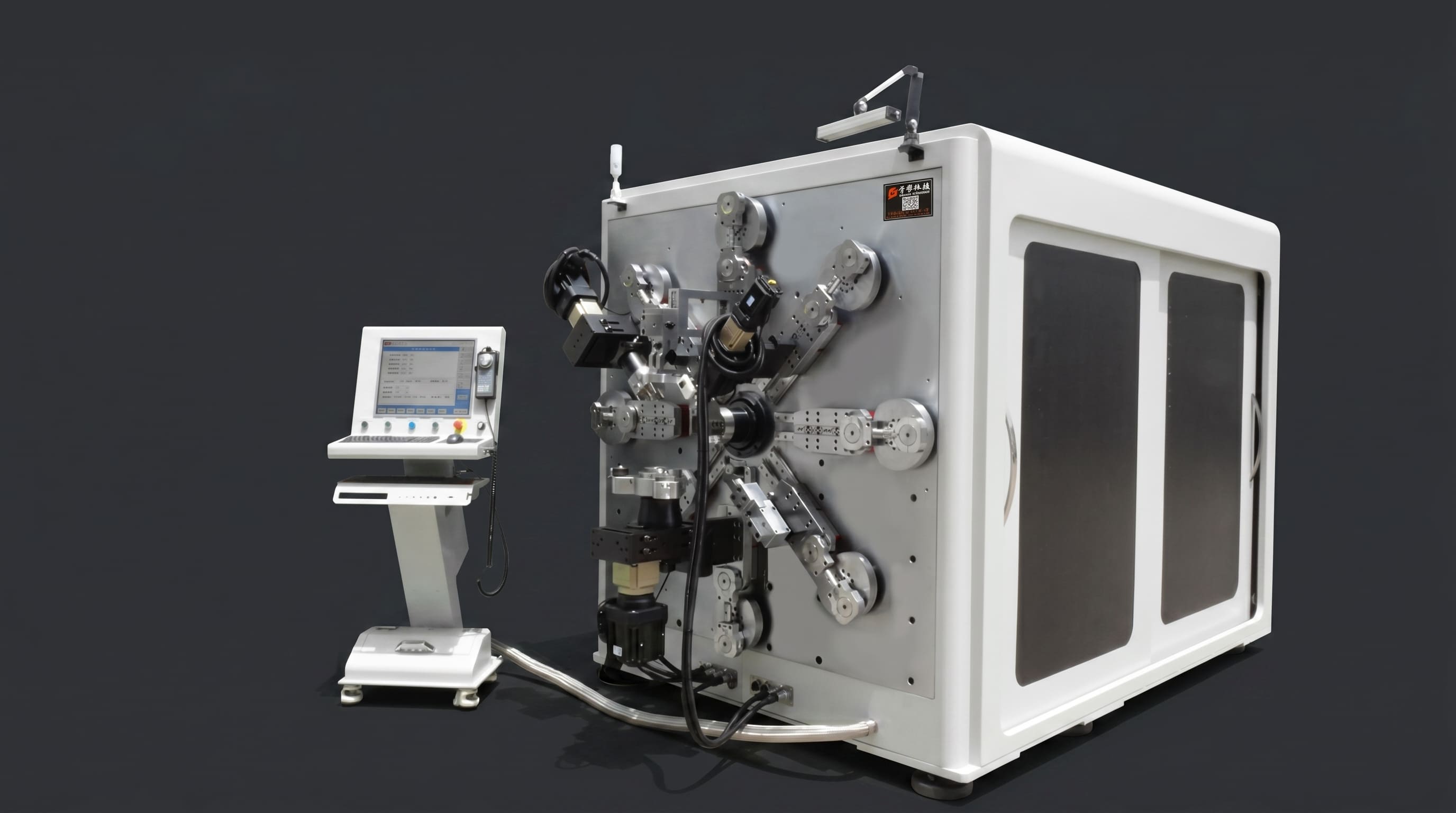
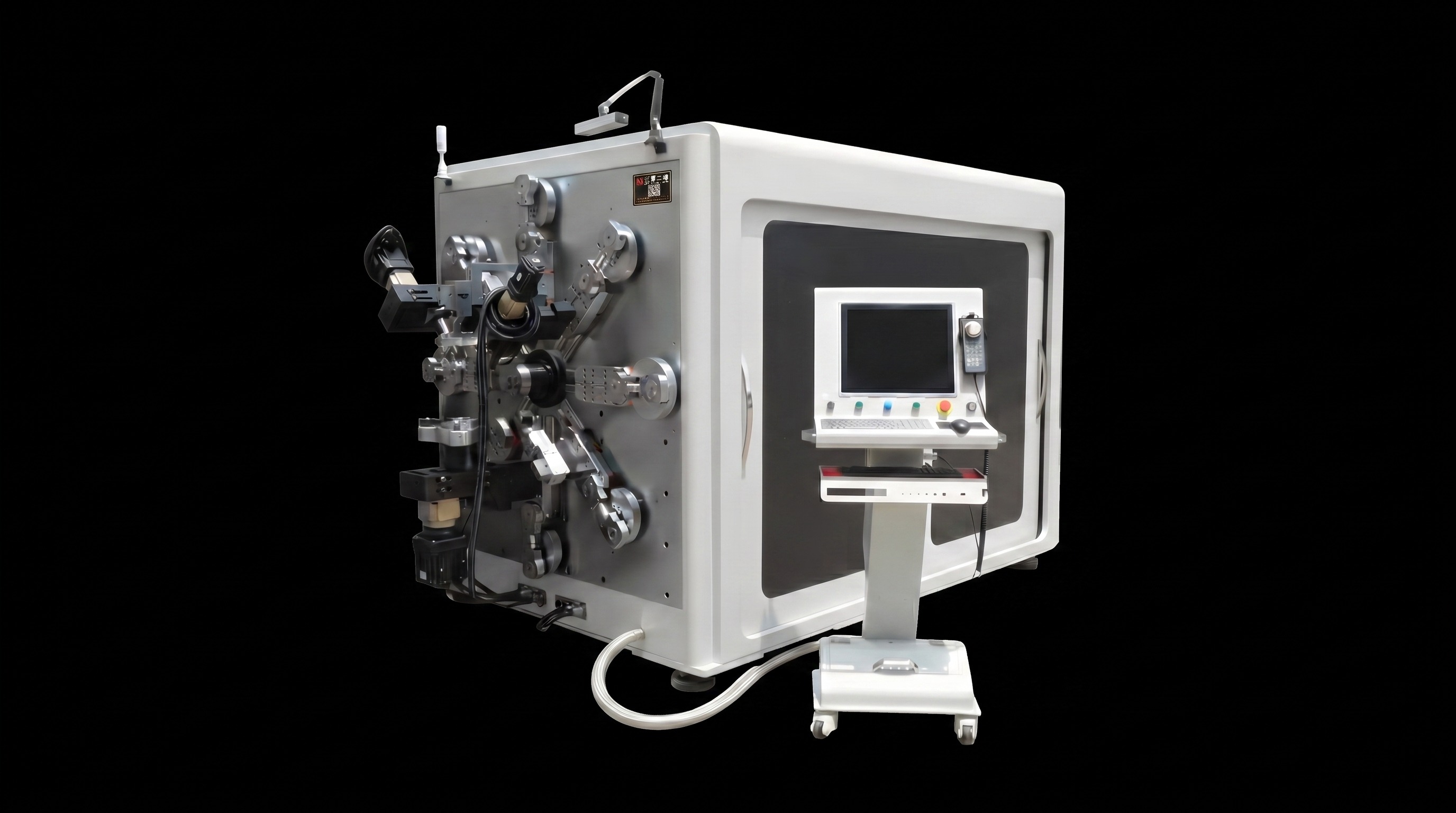
If your busbar parts combine flat bending, vertical bending, twist bending and multi‑directional transitions, it is no longer sufficient to simply check whether the machine can complete basic bends. You should prioritize auxiliary motion mechanisms and multi‑axis synchronous capability. BELAN’s solution features an 8‑arm manipulator system, two bending‑rolling units and one cutting module to build a multi‑station processing platform. Multiple robotic arms provide auxiliary positioning and assisted bending, enabling the machine to produce highly complex busbar profiles. Its key advantages are summarized below:
Comprehensive Flat, Vertical & Twist Bending
Complex busbars require continuous forming across different spatial orientations. The eight auxiliary arms support seamless transitions between flat, vertical and twist bending movements.
Short‑Distance Spatial Bending
Some components need a fast transition from flat bend to vertical bend with a very short pitch between two bending points. Single‑station machines often run out of operating space after finishing the first bend. The multi‑arm layout cooperates across independent stations to reserve enough movement clearance for tight‑spacing bends.
Assisted Forming for Special‑Shaped Workpieces
Special‑shaped copper‑aluminum busbars for EV and energy‑storage projects contain multi‑directional bends, variable angles and height offsets. Under this circumstance, the quantity of working stations and their synchronous performance carry more weight than the nominal maximum bending angle of the copper aluminum busbar bending machine.
Surface Protection Performance of Different Bending Methods
Copper and aluminum busbars, especially insulated types, have strict surface‑quality requirements. Direct die contact may leave indentations or surface scratches if pressure, clearance or mold condition is not properly controlled. Rotary bending distributes forming force through continuous movement, which can partially reduce local stress under suitable tooling and parameter settings. Servo and multi‑axis control further optimize bending speed and motion trajectory to eliminate abrupt impact on raw materials. We recommend that you do not rely purely on parameter sheets when sourcing a copper aluminum busbar bending machine. Instead, run real‑material test samples and check these key indicators: - Surface scratches - Insulation coating damage - Obvious indentations on bending zones - Stability during multi‑angle transitions - Dimensional repeatability in mass runs
Differences Between Small‑Angle, Large‑Angle and Complex 3D Bending
Small‑angle bending
Demands high positioning accuracy, material springback compensation and fast servo response.
Large‑angle bending
Reads sufficient motion space and optimized bending paths to avoid mechanical interference.
Complex 3D bending
Combines flat, vertical and twist bending. Standard 3D machines mostly rely on forward‑backward and left‑right movement of rolling heads. They are prone to space‑constraint problems when two bends are closely spaced and lack auxiliary stations for secondary forming. Multi‑station coordinated capability is therefore a vital evaluation metric for complex busbar manufacturing.
Comparison & Selection Guide of Four Bending Solutions
| Comparison Item | Die Bending | Standard Rotary Bending | Servo‑Rotary Bending | Multi‑Axis Linkage Bending |
|---|---|---|---|---|
| Standard Parts | ★★★★★ | ★★★★ | ★★★★ | ★★★★★ |
| Multi‑spec Changeover | ★★ | ★★★★ | ★★★★★ | ★★★★★ |
| Bending Precision | ★★★★ | ★★★★ | ★★★★★ | ★★★★★ |
| Complex 3D Workpieces | ★★ | ★★★ | ★★★★ | ★★★★★ |
| Flat/Vertical/Twist Bend | ★★ | ★★★ | ★★★★ | ★★★★★ |
| Die Dependency | High | Low | Low | Low |
| Automation Level | Medium | Medium | High | High |
| Auxiliary Forming for Complex Parts | Low | Medium | Medium | High |
Manufacturers with stable‑spec simple workpieces can opt for cost‑effective die‑bending or basic rotary solutions. Factories facing frequent product upgrades and complex spatial geometries should prioritize servo‑rotary and multi‑axis linkage copper aluminum busbar bending machine models.
Do Not Judge Performance Simply by Axis Quantity
The nominal axis count in equipment brochures cannot fully represent real‑world complex forming capability. You are suggested to verify these practical points: - Functions of each independent axis (feeding, bending, rotation, etc.) - Whether multi‑axes can run synchronously - Availability of independent auxiliary stations - Support for combined flat, vertical and twist bending - Mechanical‑interference risk for short‑pitch bends - Programmable continuous forming for complex profiles Submitting actual part drawings for sample trial production is far more reliable than evaluating machines only according to specification sheets.
Conclusion
Bending technology is evolving from single‑angle forming toward fully‑automatic complex 3D shaping. If your busbar products contain flat, vertical, twist bends, multi‑angle transitions and ultra‑short‑distance spatial bends, you should focus on multi‑station coordination, bending accuracy and real sample processing capacity, instead of merely comparing machine prices or advertised axis numbers. BELAN Machinery delivers professional metal forming automation solutions. If you are sourcing a copper aluminum busbar bending machine, please provide your busbar material, insulation type, 3D part drawings and monthly output requirement. BELAN will analyze your suitable bending technology, run prototype tests for complex 3D busbars and offer you a well‑matched automation proposal.
For more information or to arrange a sample test, please get in touch with our sales team.
.jpg)