
Features
Why Choose BELAN?
Multi-Axis CNC Precision Control
Advanced multi-axis CNC systems enable precise coordination of feeding, bending, rotating, cutting, and forming processes. This ensures accurate geometry, consistent quality, and stable production performance for complex wire components.
Customized Wire Forming Solutions
Belan provides customized forming solutions based on different wire materials, product structures, and production requirements. From automotive components to special wire parts and busbar applications, we help customers select the right machine configuration for their needs.
High Accuracy & Repeatable Production
Servo-controlled systems and precision mechanical structures deliver excellent feeding accuracy and bending consistency, helping manufacturers maintain stable product quality during continuous production.
Integrated Automatic Forming Process
Belan machines integrate multiple processes including wire feeding, straightening, bending, rotating, cutting, and forming into one automated workflow, reducing manual operations and improving overall production efficiency.
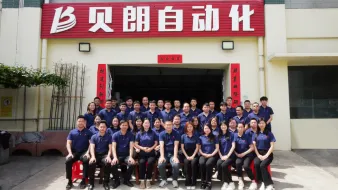
We Have The Best Solutions for Your Business
DONGGUAN BELAN AUTOMATION EQUIPMENT CO.,LTD stands at the forefront of the global wire forming industry. Located in the manufacturing heartland of Dongguan, we specialize in high-end 2D and 3D wire forming solutions that merge German precision with Chinese agility.
By integrating advanced CNC technologies from Japan and Korea, we have solved the industry's most persistent challenges: achieving micron-level precision while maintaining high-speed production stability.
Busbar Processing Machine: CNC Automation, Precision Control, and Manufacturing Excellence
The modern CNC busbar processing machine represents a convergence of precision mechanical engineering, servo motion control, and intelligent software that transforms the traditionally labor-intensive task of busbar fabrication into an automated, repeatable, and quality-controlled manufacturing process. At its core, a busbar processing machine is a multi-function CNC system that coordinates bending, punching, and cutting operations under a unified controller — but the technical sophistication beneath this simple description encompasses servo-hydraulic hybrid drives, closed-loop metrology, material-specific process models, and Industry 4.0 data integration. Belan Machinery's TP Series busbar processing machines embody this engineering approach, delivering the precision and productivity that modern electrical equipment manufacturing demands.
The Integrated Processing Architecture
The defining architectural feature of a CNC busbar processing machine is the consolidation of three distinct fabrication processes — bending, punching, and cutting — within a single machine frame, operating from a common datum and under a single CNC controller. This architecture is fundamentally different from a collection of standalone machines connected by manual material handling; it is designed around the principle that dimensional accuracy is preserved when the workpiece never leaves its reference frame.
In practice, the busbar is clamped once at the beginning of the processing cycle. The CNC controller then coordinates the sequential execution of operations: the servo back-gauge positions the busbar for the first bend; the hydraulic bending unit forms the bend to the programmed angle with real-time encoder feedback; the back-gauge repositions for the next feature — a punched hole — and the hydraulic punch unit drives the tool through the material at the precise programmed coordinate; the back-gauge advances again for the next bend or punch, and finally positions the busbar at the shear for the final cut to length. Throughout this entire sequence, the busbar's positional relationship to every tool station is maintained by the numerically controlled axes, not by operator skill or fixture transfers.
Servo-Hydraulic Drive Technology
The bending and punching force required for busbar processing demands hydraulic actuation — 15 to 45 tons for copper busbars, depending on cross-section and temper. However, the positioning accuracy and speed required for high-productivity CNC operation demands servo control. The servo-hydraulic hybrid drive resolves this apparent contradiction by combining the force density of hydraulics with the precision and energy efficiency of servo motors.
How servo-hydraulic control works: A servo motor drives a hydraulic pump directly rather than through a constant-speed induction motor. The servo motor's speed and torque are continuously varied to match the instantaneous load demand — accelerating rapidly during the bending approach, delivering high torque during the bend forming phase, and decelerating to idle between cycles. This on-demand power delivery contrasts sharply with conventional hydraulic systems where the pump runs at constant speed regardless of load, dumping excess flow through a relief valve as heat.
The quantifiable advantages of servo-hydraulic drive in busbar processing machines include: 25 to 30 percent reduction in energy consumption (measured at the main power input, comparing identical processing cycles); 10 to 15 dB(A) reduction in operating noise (particularly during idle periods between cycles); 30 to 40 percent reduction in hydraulic oil volume (since the variable-displacement pump operates at lower average flow rates); and faster cylinder response times (servo motors accelerate from zero to rated speed in under 100 milliseconds, compared to 300 to 500 milliseconds for conventional pump unloading valve transition).
CNC Axis Control: Positioning Accuracy and Repeatability
A busbar processing machine typically controls three to five numerically controlled axes, each contributing to overall part accuracy:
| Axis | Function | Drive Type | Positioning Accuracy |
|---|---|---|---|
| X-axis (back-gauge) | Longitudinal busbar positioning for bend, punch, and cut location | AC servo motor + ball screw | ±0.15 mm |
| Y-axis (bend angle) | Bend ram stroke control determining final bend angle | Servo-hydraulic cylinder | ±0.3° (via rotary encoder) |
| Z-axis (punch) | Punch ram stroke for hole creation | Hydraulic cylinder | Position by X-axis reference |
| T-axis (tool turret) | Automatic punch tool selection from multi-tool turret | Servo motor + indexer | ±0.05 mm tool alignment |
| C-axis (shear) | Cut-to-length shearing operation | Hydraulic cylinder | ±0.3 mm cut length |
The X-axis servo back-gauge is the most critical axis for overall part accuracy because it establishes the positional reference for every bend, hole, and cut on the busbar. Belan's TP Series employs an AC servo motor driving a precision-ground ball screw through a zero-backlash coupling, with position feedback from a rotary encoder mounted directly on the motor shaft (semi-closed loop) or, optionally, a linear scale mounted on the machine frame (full-closed loop) for applications requiring the highest positional accuracy. The 30 m/min rapid traverse speed ensures that positioning moves between features contribute minimally to overall cycle time.
Closed-Loop Angle Measurement and Springback Compensation
Bend angle accuracy is one of the most challenging aspects of busbar processing because the final angle depends not only on the ram stroke position but also on material springback — the elastic recovery that occurs when the bending force is released. Springback varies with material type (copper vs. aluminum), temper (annealed vs. half-hard vs. hard), cross-section dimensions, and even batch-to-batch variations within the same material specification.
A closed-loop angle measurement system addresses springback by measuring the actual bend angle in real time during the bending operation, rather than relying solely on ram position. A rotary encoder or inclinometer sensor mounted on the bending tool measures the workpiece angle throughout the bend stroke. The CNC controller compares the measured angle to the target, calculates the required overbend to compensate for springback (typically 2 to 4 degrees for copper, 1 to 2 degrees for aluminum), and commands the ram to continue past the nominal angle until the material yields to the overbend position. When the ram retracts and the material springs back, the final angle settles at the target value.
The CNC controller also maintains a springback compensation table in memory, populated during initial machine commissioning with values for each common material and cross-section combination. When the operator selects a material from the HMI touch screen, the controller automatically loads the appropriate compensation factors. For new materials not yet characterized, the teach-in function executes a test bend, measures the resulting springback, and automatically adds the value to the compensation table — building the machine's material intelligence with each new application.
Tooling Systems and Rapid Changeover
The productivity of a busbar processing machine in high-mix production depends heavily on tooling changeover efficiency. When a panel builder produces 30 to 50 unique busbar designs per day — each potentially requiring different bend radii, hole diameters, and cut specifications — the time spent changing tools between jobs directly impacts the number of busbars the machine can process per shift.
Bend dies are designed for quick-change mounting using mechanical clamping rather than bolted connections. A typical die change — for example, switching from a 6 mm bend radius die (for 30×5 mm copper) to an 8 mm radius die (for 50×6 mm copper) — requires loosening one or two clamp levers, sliding out the old die set, inserting the new one, and re-tightening. Total time: 45 to 90 seconds with an experienced operator.
Punch tools are organized in a multi-station turret that indexes automatically under CNC control. When the busbar program calls for a 9 mm hole rather than an 11 mm hole, the turret rotates to the correct tool station without operator intervention. A typical turret carries 6 to 8 tool stations, covering the most common busbar hole sizes (6, 7, 9, 11, 13, 17, 21 mm) without requiring manual tool changes. For hole sizes outside the turret range, individual tool changes are executed using quick-release punch holders that allow pin-and-die swaps in 60 to 90 seconds per station.
Shear blades require periodic sharpening (typically every 10,000 to 20,000 cuts for copper, more frequently for harder tempers) and eventual replacement. The blade mounting system is designed for straightforward removal — typically four to six socket-head cap screws — with blade replacement completed in 15 to 20 minutes including alignment and clearance adjustment.
CAD-to-Part Digital Workflow
The digital integration between the electrical design office and the busbar processing machine is what transforms a CNC machine from a standalone fabricator into a node in a digital manufacturing chain. The workflow that connects the engineering drawing to the finished busbar follows a structured sequence:
Step 1 — Design export: The electrical engineer creates the busbar design in EPLAN, AutoCAD Electrical, SolidWorks Electrical, or a similar ECAD/MCAD platform. The busbar flat pattern — showing all bend lines, hole positions, and trim lines in a single 2D view — is exported as a DXF (Drawing Exchange Format) file. This is a standard CAD interchange format supported by virtually all electrical and mechanical design software.
Step 2 — File transfer: The DXF file is transferred to the busbar processing machine via USB flash drive or Ethernet network connection. Ethernet enables direct file access from a shared network folder, allowing the machine operator to retrieve the latest revision of each busbar design without manual file copying.
Step 3 — Automatic feature extraction: The CNC controller's DXF import module analyzes the 2D drawing, identifying geometric features by their CAD entity types. Bend lines (typically drawn on a dedicated layer or with specific line types) are recognized and their coordinates extracted. Circles representing holes are identified by diameter and center position. Trim lines indicating the cut-to-length position are recognized. The software applies configurable rules — for example, recognizing that a circle entity of 9 mm diameter on a specific layer represents a bolt hole to be punched with the 9 mm tool.
Step 4 — Sequence optimization: The controller generates an optimized processing sequence based on machine kinematics. For parts with both bends and holes, the sequencer determines the most efficient order — typically punch-first for holes located away from bend zones (to avoid tool interference with previously formed bends), or bend-first if hole positions are referenced from a datum that is more stable before bending. The optimization algorithm considers tool change time, back-gauge traverse distance, and the physical constraints imposed by the machine's tool layout.
Step 5 — Simulation and verification: Before cutting material, the operator views a graphical simulation of the complete processing sequence on the CNC touch screen display. The simulation shows the busbar moving through each bend, punch, and cut operation, with dimensional callouts for each feature. This visual verification catches programming errors — incorrect bend direction, missing holes, wrong cut length — before any material is processed, contributing to the machine's sub-0.5 percent scrap rate.
Step 6 — Production execution: With the program verified, the operator loads the correct material (specified by the program's material selection — copper or aluminum, temper, dimensions) and initiates the automatic cycle. The machine executes the complete sequence without further operator intervention, while the HMI displays real-time status including current operation, remaining cycle time, and part count.
Production Data Management and Quality Traceability
As electrical equipment manufacturing moves toward Industry 4.0 principles, the busbar processing machine is evolving from a standalone production tool into a connected data source within the factory's digital ecosystem. Modern CNC controllers log production data that supports quality traceability, process optimization, and regulatory compliance:
- Part-level traceability: Each processed busbar is logged with a timestamp, program number, operator ID, material batch identifier, and the measured values from any in-process checks (bend angle verification, hole diameter go/no-go). For industries requiring full material traceability — EV battery manufacturing under IATF 16949, aerospace under AS9100 — this data supports the documentation of every busbar from raw material receipt through finished assembly.
- Process capability monitoring: Statistical process control (SPC) functions track critical dimensions over time — bend angle variation, hole positional deviation, cut length consistency — and generate control charts that alert operators to process drift before it produces out-of-tolerance parts. This is particularly valuable for high-volume production lines where manual inspection of every part is impractical.
- Maintenance scheduling: The CNC tracks machine utilization hours, cycle counts, and tool wear indicators (punch cycles per tool, bend die cycles), generating predictive maintenance alerts based on configurable thresholds rather than fixed calendar intervals. This condition-based approach reduces both unplanned downtime and unnecessary preventive maintenance.
- Energy consumption monitoring: Servo-hydraulic machines with integrated power monitoring can report energy consumption per busbar, per shift, and per material type — data that supports sustainability reporting, ISO 50001 energy management, and cost allocation to specific production orders.
Automation Integration: From Standalone to Production Cell
A busbar processing machine can operate as a standalone workstation — operator loads raw busbars, machine processes them, operator unloads finished parts — or as the core of an automated production cell. The level of automation is determined by production volume and the economic justification for reducing manual labor.
Level 1 — Manual loading: The operator loads each busbar individually into the machine's infeed guide. Suitable for low-to-medium volume (up to 200 busbars per shift) where the incremental cost of automation exceeds the labor saving.
Level 2 — Powered infeed with material magazine: A powered roller conveyor feeds busbars from a gravity or powered magazine into the processing machine. The operator loads batches of 20 to 50 busbars into the magazine and attends to other tasks while the machine processes them sequentially. Throughput gain: approximately 15 to 20 percent over manual loading, primarily from eliminating the operator wait time between cycles.
Level 3 — Robotic loading and unloading: An industrial robot (typically a 6-axis articulated arm) picks raw busbars from an input pallet, presents them to the processing machine's infeed, and places finished busbars onto an output pallet or conveyor. The robot can also perform secondary operations such as sorting finished busbars by part number into separate collection bins, applying identification labels, or stacking busbars in assembly kit sequence. Throughput gain: 50 to 80 percent over manual loading, with the additional benefit of lights-out operation — the cell can continue processing after the end of the operator shift, limited only by the capacity of the input and output buffers.
Precision Verification and In-Process Quality Control
While the CNC busbar processing machine's axis accuracies define its capability, the actual quality of processed busbars depends on systematic verification practices. A comprehensive quality control protocol for busbar processing includes:
First-article inspection: The first busbar produced from each new program or after a tooling change undergoes a complete dimensional check against the engineering drawing. Critical dimensions — bend angles (verified with a digital protractor, ±0.1° resolution), hole positions (verified with a coordinate measuring machine or digital height gauge, ±0.01 mm resolution), cut length (verified with a calibrated tape or digital caliper) — are recorded on the first-article inspection report. Only after the first article passes inspection is production released.
In-process sampling: At defined intervals — typically every 20 to 50 parts or every 2 hours of continuous operation — a sample busbar is pulled from production and checked for the most critical dimensions. This sampling plan is based on the process capability (Cpk) established during machine qualification: a process with Cpk ≥ 1.67 requires less frequent sampling than one with Cpk of 1.33 to 1.67.
Tool wear monitoring: Punch tool condition is monitored by the hole quality on processed busbars — burr height on the exit side of the hole (measured with a burr gauge), hole diameter (checked with go/no-go plug gauges), and the roundness of the hole (visual inspection under magnification for critical applications). When burr height exceeds the acceptance criterion (typically 0.05 mm for bolted connection surfaces), the punch pin and die are sharpened or replaced.
For applications requiring full process documentation — such as busbars for EV battery packs subject to IATF 16949 quality management — Belan's TP Series machines can be configured with data logging that records the actual measured values from in-process checks, creating a digital quality record for every production batch that satisfies the traceability requirements of automotive and aerospace quality standards.
Maintenance and Reliability Engineering
A busbar processing machine's long-term reliability is a function of its engineering design, component quality, and the rigor of its maintenance program. Key reliability considerations include:
Frame and structural integrity: The machine frame — typically a welded steel fabrication — must maintain dimensional stability under cyclic loading over decades of operation. Post-weld stress relief (thermal treatment at 550–600°C followed by controlled cooling) minimizes residual stresses that could cause gradual frame distortion. Belan's TP Series frames undergo this treatment and are machined on precision CNC milling centers after stress relief to establish flat, square mounting surfaces for all motion axes and tool stations.
Hydraulic system design: The hydraulic power unit — pump, motor, valves, reservoir, filtration — must deliver consistent pressure and flow over millions of cycles. Design features that promote reliability include: 10-micron absolute filtration on the return line to remove wear particles before they re-enter the pump; oil temperature monitoring with automatic cooling fan activation above 50°C; hard-chrome-plated cylinder rods for corrosion and wear resistance; and high-quality seals (polyurethane or PTFE compound) rated for the system's maximum pressure and temperature.
Preventive maintenance schedule: A structured maintenance program — daily, weekly, monthly, quarterly, and annual tasks — is essential for sustaining the machine's accuracy and uptime. Daily tasks include cleaning the work area of copper chips and debris, checking hydraulic oil level, and verifying the function of safety interlocks. Weekly tasks include lubricating ball screw and linear guide bearings, inspecting punch tool condition, and checking back-gauge alignment with a dial indicator. Quarterly tasks include changing hydraulic oil filters, checking electrical connections for tightness, and verifying CNC program backup. The complete maintenance schedule is documented in the machine's operation manual, with checklists that support ISO 9001 maintenance record-keeping requirements.
Selecting a Busbar Processing Machine for Precision Manufacturing
The decision to invest in a CNC busbar processing machine is fundamentally a manufacturing strategy decision — it represents a commitment to precision, repeatability, and process control over manual methods. When evaluating a specific machine, the technical evaluation should address:
- Axis accuracy verification: Request documented positioning accuracy data — not just the specification sheet value, but actual measurement data from the machine's factory acceptance test (FAT). A laser interferometer measurement of the X-axis back-gauge over its full travel range provides objective evidence of positioning performance.
- Process capability demonstration: During the machine demonstration or acceptance test, run a capability study on a representative busbar — process 30 to 50 consecutive parts and measure critical dimensions to calculate Cpk values. A capable process (Cpk ≥ 1.33) demonstrates that the machine's inherent accuracy translates into consistent production quality.
- Software and DXF import compatibility: Test the DXF import function with actual CAD files from your design software — not just with the manufacturer's demonstration files. Minor differences in CAD entity types, layer naming, or coordinate systems can cause import failures that only surface with real production data.
- Global service infrastructure: Verify the manufacturer's spare parts stocking policy, typical lead time for critical components (hydraulic pump, CNC controller, servo drive), and the availability of remote diagnostic support. Belan provides comprehensive global support with 3-to-7-day air courier spare parts delivery to major industrial markets.
Belan Machinery's engineering team provides detailed technical consultation for busbar processing machine selection, including application analysis, capacity recommendations, tooling configuration, and ROI projections based on your specific production data. Explore the complete TP Series busbar processing equipment range to compare specifications across models, review technical articles and application case studies, or contact Belan directly to discuss your manufacturing requirements with a busbar processing specialist.
Featured Products
Collection about BELAN
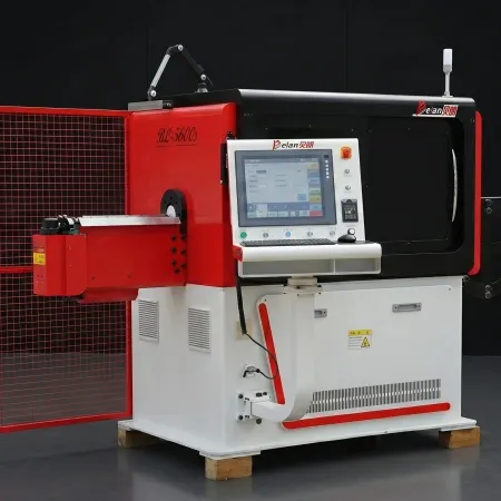
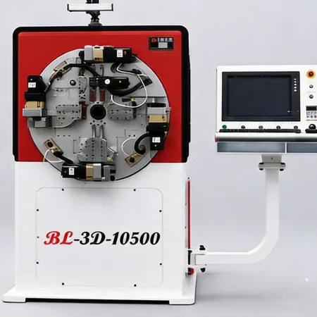
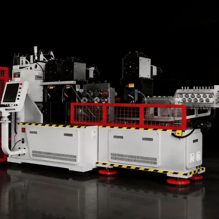
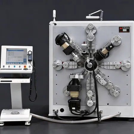
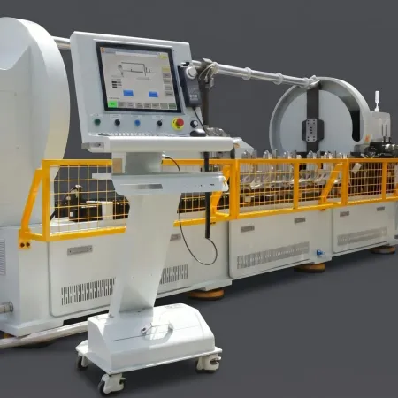
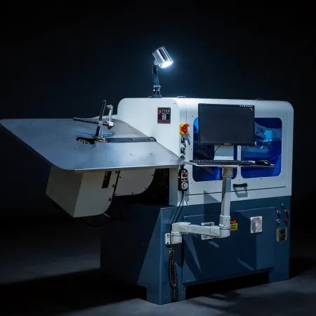
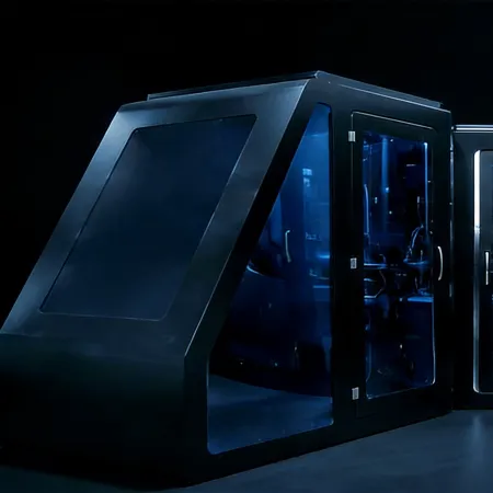
User Reviews
What users say about BELAN
Frequently Asked Question
Do you have any question?
A busbar processing machine is automated equipment designed to process copper and aluminum busbars through operations such as bending, forming, cutting, and positioning. These machines help electrical and EV manufacturers improve production efficiency and maintain consistent processing quality.
A busbar bending machine mainly focuses on precision bending operations, while a busbar processing machine refers to equipment that can perform multiple busbar manufacturing processes. Depending on production requirements, a processing machine may include bending, cutting, punching, and forming functions.
Most busbar processing machines are designed for conductive materials such as copper and aluminum. The suitable processing range depends on the machine configuration, including busbar width, thickness, material properties, and required forming operations.
Busbar processing machines are widely used in EV battery systems, electrical cabinets, switchgear, renewable energy equipment, power distribution systems, and industrial electrical manufacturing.
CNC busbar processing machines provide higher accuracy, repeatability, and production efficiency by automating positioning and forming processes. They reduce manual adjustment and help manufacturers maintain stable quality during large-volume production.
Yes. Belan provides customized CNC busbar processing solutions according to busbar dimensions, material types, production requirements, and application scenarios.
Our updates and blog posts
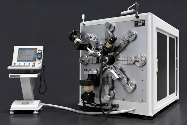
Busbar Bending Machine: CNC Precision Engineering for Modern Power Distribution Manufacturing
Complete guide to CNC busbar bending machines: types, components, materials, bend types, applications, quality standards. Belan TP Series. CE and ISO 9001.
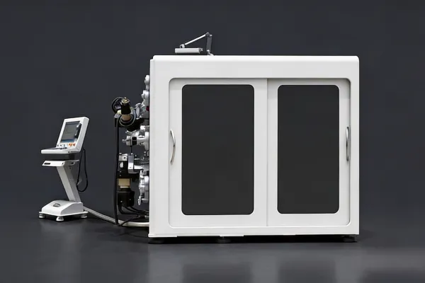
Busbar Bending Machine: CNC Precision Engineering | Belan
CNC busbar bending machine technology: servo-hydraulic systems, closed-loop angle measurement, springback compensation, CAD integration. Belan TP Series.