

CNC wire bending machines have become essential equipment in modern metal fabrication because they replace slow, operator-dependent manual bending with automated, repeatable wire forming. From automotive seat frames, wiper linkage arms and suspension wires to furniture hardware, industrial brackets and electrical components, these machines convert coiled wire into precise two-dimensional or three-dimensional shapes with less manual intervention and tighter dimensional consistency. This guide explains what a CNC wire bending machine is, how the machine works stage by stage, what the main components and axis configurations mean in practice, and how manufacturers should evaluate and select the right equipment for their wire products.
Most of the wire components around us are formed, not just cut. The frame inside a car seat, the hangers that suspend an exhaust system, the clips and brackets inside household appliances, and the wire structures used in storage and display systems all start as coiled wire that must be fed, straightened, bent and cut into shape. When production volumes grow, manual bending against jigs and templates cannot keep up: cycle times are long, dimensions drift with operator skill, and changeover between products is slow. Understanding how a CNC wire bending machine performs these operations automatically is the first step toward choosing equipment that matches both your parts and your production targets.
What Is a CNC Wire Bending Machine?
A CNC wire bending machine is an automated forming machine that uses computer numerical control to bend metal wire into programmed two-dimensional or three-dimensional geometries. The machine combines automatic wire feeding, a servo-controlled system and programmable forming tools to produce finished wire components with repeatable accuracy. Instead of a skilled operator bending each piece against a fixture, the operator loads a forming program, the machine pulls wire from a coil, and every bend, rotation and cut is executed automatically in sequence.
The difference from manual bending is not only speed; it is consistency. A manual process depends on the operator to position the wire, apply the same force and check every angle, and small variations accumulate across a production run. A CNC process defines feeding length, bend angle and tool movement numerically, so the first part and the ten-thousandth part follow the same motion program. This repeatability is the main reason CNC wire forming has become standard in automotive, furniture, appliance and hardware production, where downstream assembly expects identical parts in every batch.
How Does a CNC Wire Bending Machine Work?
A CNC wire bending machine works by coordinating a sequence of automated operations: wire feeding, straightening, positioning, bending, rotating or forming, and finally cutting. Each stage is controlled by the CNC system and executed by servo-driven mechanisms, and the whole cycle runs without manual intervention. The sections below describe each stage of the production workflow.
Wire Feeding
Wire feeding is the first operation. The machine pulls wire from a coil through a feeding mechanism driven by a servo motor, which controls exactly how much wire advances into the forming area. Feeding length is a program value: the CNC system knows how much material each bend consumes and advances precisely that distance. Feeding accuracy matters because every bend position is measured along the wire length, and an error in feeding is multiplied by every subsequent bend. This is why servo-driven feeding is preferred over mechanical feed systems on machines that must hold tight dimensional tolerances.
Wire Straightening
Wire stored on a coil carries residual curvature and spring deformation from the coiling process. If this curve remains in the wire when it reaches the bending head, bend positions and angles become inconsistent. Before forming, the machine passes the wire through a straightening unit that removes the coil deformation and makes the material run true. Straightening improves dimensional consistency across the whole component and prepares the wire for accurate positioning and bending, especially for longer parts where even a small initial curve is amplified along the length.
Positioning and CNC Control
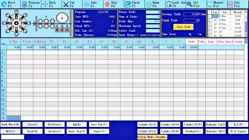
The CNC control system is the brain of the machine. It determines the feeding distance for each segment, the bending position along the wire, the bending angle, any rotation of the bending head, and the cutting position. Operators create or load a forming program that lists these values for every step, and the control system coordinates the servo drives so that each movement happens in the correct sequence and at the correct moment. Because all positions and angles are numeric values stored in the program, the same part can be reproduced exactly on any shift, by any operator, and refined easily when the part design changes.
Wire Bending and Forming
The actual geometry is created at the bending and forming units. A bending head, driven by a servo motor, presses the wire around a bending tool to the programmed angle. On multi-axis machines, the head can also rotate and reposition so that bends are made in different planes, producing true three-dimensional shapes. Different machine configurations support different levels of forming complexity: simple two-dimensional parts can be produced on compact 2D machines, while complex three-dimensional components with bends in several planes require machines with more axes and a rotating head. The tooling, including bending pins and forming dies, is selected to match the wire diameter and the bend radius of the part.
Cutting and Finished Product Output
After the last bend is completed, an automated cutting unit separates the finished component from the remaining wire. Cutting is synchronized with the forming sequence, so the machine produces parts back to back with no pause between cycles. The finished component is ejected or dropped into a collection bin, and the next component begins feeding immediately. This closed loop from coil to finished part eliminates most manual handling: operators supervise the machine, monitor quality and change coils, rather than positioning, bending and cutting each piece by hand.
What Are the Main Components of a CNC Wire Bending Machine?
A typical CNC wire bending machine is built from several coordinated systems. Understanding what each system does helps buyers compare machines and judge which configuration suits their production.
CNC Control System
The control system runs the forming program, coordinates all axes and records production data. It is where operators load programs, set parameters and monitor the machine during operation.
Servo Motors and Drives
Servo motors power the feeding, bending, rotating and cutting movements with closed-loop position control. The servo-controlled system is what gives the machine its forming accuracy and its ability to repeat the same movement precisely on every cycle.
Wire Feeding System
The feeding system draws wire from the coil and advances a controlled length for each step. Feeding accuracy is a key machine specification, because it directly determines how accurately bend positions are located along the wire.
Bending and Forming Units
The bending head and forming tools create the actual geometry. The head presses the wire around the bending tool to the programmed angle, and on multi-axis machines it can also rotate to form bends in different planes.
Cutting System
The cutting unit separates the finished component from the wire supply after the forming sequence is complete. Cutting is integrated into the cycle so the machine runs continuously without manual separation.
Automatic Feeder
Many machines can be equipped with an automatic feeder that holds the wire coil and guides the wire into the machine without operator attention. This is what allows long unattended runs, since the machine keeps processing wire until the coil is exhausted.
2D vs. 3D CNC Wire Bending Machines
CNC wire bending machines are commonly grouped into two classes based on the geometry they produce. A 2D wire bending machine forms bends in a single plane: the wire stays flat, and the finished part can be laid on a table. A 3D wire bending machine adds rotation of the bending head, so bends can be made in multiple planes and the finished part occupies three-dimensional space. The table below compares the two classes.
| Feature | 2D Wire Bending | 3D Wire Bending |
|---|---|---|
| Forming direction | Mainly planar | Multi-directional |
| Product geometry | Relatively simple | More complex |
| Typical applications | 2D brackets and simple wire parts | Automotive and complex wire components |
| Axis requirements | Generally lower | Generally higher |
| Production flexibility | Suitable for planar products | Suitable for complex 3D products |
Neither class is universally better. A part that only needs flat bends is produced more economically on a 2D machine, while a part with bends in several planes requires 3D capability. Machine selection should be driven by the product geometry: examine the component, count the planes in which bends occur, and choose the machine class that can form it within tolerance. For a closer look at what three-dimensional forming adds, see our article on the advantages of 3D wire bending machines.
What Does the Number of CNC Axes Mean?
In a CNC wire bending machine, an axis is an independently controlled movement: feeding the wire, rotating the head, bending, and other motions each count as axes. Machines are commonly described by their axis count, such as 3-axis, 5-axis or 6-axis configurations. A 3-axis 2D machine typically controls feeding, bending and cutting to produce flat parts. A 5-axis or 6-axis machine adds rotary and positioning movements that allow bends in multiple planes, which is the basis of three-dimensional forming. Multi-axis systems with more axes, such as the dual-head machines used for long automotive components, coordinate an even larger set of movements.
More axes provide greater movement coordination and forming flexibility, but they do not automatically make a machine better. The correct axis configuration depends on the product: a part with simple flat bends does not benefit from extra axes, while a complex three-dimensional component cannot be produced without them. When evaluating machines, define the forming operations your parts actually require and match the axis configuration to those operations, rather than selecting a machine by axis count alone.
What Types of Wire Can CNC Wire Bending Machines Process?
A machine's wire range is defined by several factors: wire diameter, wire material, whether the wire is soft or hard, the section shape, and the geometry of the finished part. The diameter range is usually published as two values, one for soft wire and one for hard wire, because harder material is more difficult to bend and requires more forming force. Within those limits, machines typically process round steel wire, stainless steel wire and other common wire materials; special-profile material such as flat wire or coated wire requires machines with appropriate feeding and forming tooling.
Belan's range illustrates how machines are matched to wire. The BL-2D-3800 2D machine processes soft wire from Φ3.0 to 8.0 mm and hard wire from Φ3.0 to 6.0 mm. The BL-3D-6250 is a small-diameter 6-axis machine for soft wire from Φ1.6 to 3.5 mm and hard wire from Φ1.6 to 2.5 mm. The dual-head BL-2T-15600 handles soft wire from Φ3.0 to 6.0 mm and hard wire from Φ3.0 to 4.5 mm. Each machine is engineered around a specific wire envelope, which is why matching the machine to your wire specifications matters more than any single headline feature.
For materials outside round wire, such as the copper and aluminum busbar used in electrical distribution, dedicated processing equipment is required. Belan also offers a busbar bending machine designed for these flat conductors. The key principle for any wire product is the same: confirm the material, diameter or section, and geometry first, then select a machine whose published range covers your requirements with a safety margin.
What Products Can Be Made with CNC Wire Bending Machines?
CNC wire forming technology is used across many industries. The application areas below are where Belan machines are actively applied.
Automotive Wire Components
Automotive manufacturing is one of the largest users of CNC wire bending. Typical components include seat frame wire, rear seat wire frames, foam seat support wires, wiper linkage arms, exhaust hangers, automotive linkage rods and seat support structures. These parts are produced in large volumes and must meet tight dimensional tolerances, which makes automated wire forming the standard production method. Machines are selected according to the component: small-diameter suspension wires suit a 6-axis machine such as the BL-3D-6250, while long symmetrical frames benefit from a dual-head machine that bends both ends in one cycle. More detail is available on the automotive parts wire forming solution page, and a real production example is documented in the automotive seat grid plate bending case study.
Industrial Wire Components
Outside the automotive sector, CNC wire bending machines produce industrial brackets, wire structures and hardware components for furniture, appliances, storage and display systems, kitchen accessories and similar products. These parts are often simpler than automotive components, which makes them well suited to 2D machines with high feeding speed and efficient cycles. Belan's industrial wire forming solutions page describes how wire forming equipment is applied across these product families, and the steel wire and iron wire bending case study shows a typical hardware production application.
How to Choose the Right CNC Wire Bending Machine
Purchasing a wire bending machine is a long-term decision, and the machine will define your production capability for years. The following factors should be documented before evaluation begins.
- Wire diameter. Match the machine's soft and hard wire ranges to the largest and smallest diameter you produce. Running at the edge of a published range invites forming problems.
- Wire material. Soft wire, hard wire, stainless steel and coated wire behave differently during bending. Confirm that the machine and its tooling suit your material.
- Product geometry. Flat parts suit 2D machines; parts with bends in multiple planes require 3D capability. Count the planes before comparing machines.
- Required number of axes. Define the forming operations your parts need and select the axis configuration that covers them, no more and no less.
- Production volume. High volumes justify machines with automatic feeding and fast cycles; low volumes may be served by simpler, more flexible configurations.
- Automation requirements. Decide whether the line must run unattended, which drives requirements for automatic feeders, part collection and monitoring.
- Required feeding and bending accuracy. Feeding accuracy locates bend positions; bending accuracy determines angles. Specify the tolerances your parts demand.
- Machine configuration and tooling. Consider frame rigidity, the servo system, tooling availability and the supplier's support for application-specific tooling.
When these factors are documented, a supplier can match your parts to the correct platform and design the tooling that produces them within tolerance. The machines in the next section show how configuration follows the application.
CNC Wire Bending Machine Applications at Belan
Belan's wire bending machine range covers the main production scenarios described in this guide, from compact 2D forming to small-diameter 3D bending and dual-head forming of long components. The three machines below are representative examples of how configuration follows the part.
The BL-2D-3800 is a 3-axis 2D CNC wire bending machine for planar wire components. It processes soft wire from Φ3.0 to 8.0 mm and hard wire from Φ3.0 to 6.0 mm, with wire feeding speeds up to 90 m/min and ±0.1 mm feeding accuracy, powered by a 6.5 kW servo system. With integrated feeding, bending and cutting, it suits manufacturers producing automotive clips, furniture hardware, wire brackets and other 2D parts in medium to high volumes.
The BL-3D-6250 6-axis CNC wire bending machine is designed for small-diameter wire processing: soft wire from Φ1.6 to 3.5 mm and hard wire from Φ1.6 to 2.5 mm, with a 580 mm bending stroke and 5.6 kW total power. Its multi-axis control performs complex three-dimensional bends while keeping dimensional consistency, which makes it a practical choice for seat suspension wires, foam seat support wires, fuel tank float rods and other precision small wire components.
The BL-2T-15600 is a 15-axis dual-head CNC wire bending machine for long and symmetrical workpieces. It processes soft wire from Φ3.0 to 6.0 mm and hard wire from Φ3.0 to 4.5 mm, with a maximum processing length of 2000 mm and 26.9 kW total power. The two synchronized bending heads form both ends of a component in a single cycle, which keeps left and right sides dimensionally identical and shortens cycle time for rear seat wire frames, seat frames, linkage rods and similar parts.
These examples show the same principle from different angles: the wire envelope, part geometry and production requirements decide the machine. Comparing the BL-2D-3800, BL-3D-6250 and BL-2T-15600 side by side, it is clear that no single configuration covers every product, and that a correct match starts with your wire specifications.
Why CNC Wire Bending Is Important for Automated Manufacturing
Moving wire forming from manual to CNC automation changes the economics of production. Manual operations are reduced to supervision and coil changes, forming becomes consistent from part to part, and repeatability is built into the process rather than dependent on operator skill. Production efficiency rises because the machine runs continuously, and product changeover becomes a matter of loading a program and adjusting tooling instead of reworking fixtures.
For manufacturers producing several wire products, flexibility is the quiet benefit of CNC forming. The same machine can run a seat frame program in the morning and a bracket program in the afternoon, which lets plants consolidate part numbers, reduce work-in-process inventory and respond faster to new samples and design changes. Complex wire geometries that are impractical to produce manually become routine, and the documented, programmable process supports quality systems and customer audits. These are the reasons CNC wire bending has moved from an option to an expectation in automated manufacturing.
Conclusion
A CNC wire bending machine is essentially a combination of automatic wire feeding, CNC control, servo movement, bending, forming and cutting, coordinated into one continuous cycle. Choosing the right machine is not about picking the largest axis count or the fastest feed speed; it is about matching the equipment to your wire material, wire dimensions, product geometry, production volume and required forming operations.
Get a Suitable CNC Wire Bending Solution
BELAN Machinery, a professional provider of automotive wire forming solutions.
If you are evaluating wire bending equipment, start by defining your wire specifications and part drawings. Contact Belan to discuss your wire components and receive a suitable CNC wire bending solution matched to your production requirements.
Contact Belan for a Customized Wire Forming Solution